Having worked in the field of electronic design for many years, I know firsthand that many novice engineers and even some with several years of experience have all been puzzled by small components on circuit boards marked “4R7,” “2R2,” or “100.” What exactly do these numbers represent? Which one should you choose when selecting an inductor?
(★ If you want to know more information, you can refer to the following article: •Inductors are Used in High Frequency Circuits and Switching Power Supplies)
After all, inductors are not as conspicuous on a circuit board as capacitors or resistors; however, choosing the wrong inductor can lead to a range of problems, from excessive power supply ripple (causing EMC test failures) to severe system instability and frequent crashes.
Let’s explore this topic from a practical application perspective and take a closer look at the three most common types of SMD inductors. By the end of this article, you will know how to avoid making these same selection errors in the future.
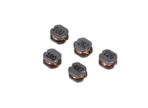
First, understand what the markings mean. Don't confuse inductors and resistors.
Many beginners often confuse these three markings with resistors when they first encounter them. After all, resistors often use the same marking format. In reality, the marking system used in the inductor industry was specifically designed to accommodate the printing requirements of small surface-mount inductors, and the rules are actually quite easy to remember:
For products with a model number containing the letter “R,” the “R” represents the decimal point, and the default unit is microhenries (μH). Thus, 4R7 corresponds to 4.7 μH, and 2R2 corresponds to 2.2 μH—it is very easy to understand.
So, why isn’t “100” interpreted as 100 µH? This follows the three-digit coding convention for surface-mount components: the first two digits represent the significant figures, and the last digit represents the power of 10. Therefore, “100” corresponds to 10 × 10⁰ = 10 µH. Although a resistor marked “100” indicates 10 Ω, the two are easily distinguished by context—specifically, the component’s location in the power path and its package (the package is much thicker than that of a resistor with the same pin configuration).
Here’s a simple summary to help you remember:
| Inductor Marking | Actual Inductance Value | Marking Rules |
| 4R7 | 4.7μH | “R” represents the decimal point; unit is μH. |
| 2R2 | 2.2μH | “R” represents the decimal point; unit is μH. |
| 100 | 10μH | Three-digit code: First two significant digits × 10^(last digit). |
Detailed analysis of application scenarios: Where are the 4R7, 2R2, and 100 inductors used?
Inductance directly determines a component’s electrical characteristics, and requirements vary significantly across application scenarios. Let us analyze, one by one, several of the most common situations encountered in practical applications:
4R7 Inductor (4.7μH): A Versatile All-Rounder with Medium Inductance
The 4.7μH (4R7) inductor is one of the most commonly used specifications in electronic design, falling within the medium-inductance range; it balances energy storage capability with high-frequency response, making it the preferred choice for many low-to-medium-current power supply circuits.
Based on my practical project experience, the most common application for a “4R7” inductor is as an energy-storage component in DC-DC converters (whether buck or boost circuits). This inductance value is well-suited for most common switching frequencies, ranging from a few hundred kHz to around 1 MHz. It effectively smooths output current and suppresses ripple without consuming excessive board space, making it an excellent fit for the increasingly compact PCB designs required today.
Typical application scenarios include the following:
Low-to-medium power modules for smartphone and tablet motherboards, designed to power components such as peripheral interfaces and baseband chips.
Power management circuits for compact, portable devices such as TWS earbuds and smartwatches.
Signal filtering for standard audio equipment, designed to suppress high-frequency noise caused by power-supply coupling.
For the main power-supply step-down module and communication data-link filtering of industrial drones, I previously came across an industrial inspection drone that used the JC0630HP-4R7MT integrated molded inductor. The integrated molded structure is vibration-resistant, has low DCR, and can extend battery life, making it very suitable for outdoor flight scenarios.
The standout advantage of the 4R7 is its versatility; with its moderate inductance value, it is well-suited for the vast majority of standard power supply applications. If you are unsure which inductance value to choose, the 4R7 is a safe bet—you generally can’t go wrong with it.
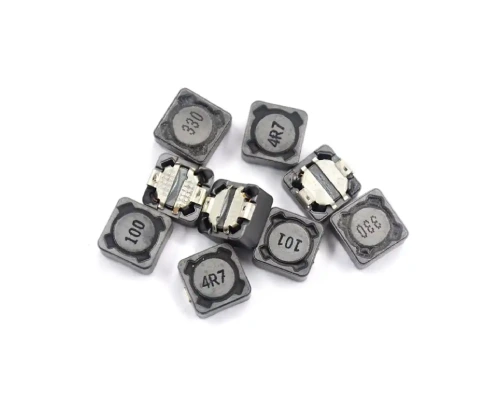
2R2 Inductor (2.2μH): The Ideal Choice for High-Frequency, High-Current Applications
The 2R2 is a 2.2μH inductor with lower inductance than the 4R7, which translates to superior high-frequency response characteristics and a higher saturation current rating; consequently, it has become an indispensable component for powering an increasing number of high-performance chips.
Low inductance implies less resistance to changes in current and faster response speeds; this is ideally suited for modern CPU and GPU chips operating at switching frequencies in the megahertz (MHz) range or higher, and it enables the system to handle sudden load fluctuations without significant voltage overshoot.
The most common 2R2 application scenario in real projects:
Multi-phase power circuits for laptop CPUs and GPUs (including those with discrete graphics); as chip power consumption rises, high-current, low-inductance inductors are required to support high-frequency switching.
Voltage Regulator Modules (VRMs) for high-end processing chips, such as FPGAs and AI chips.
High-density power modules for automotive electronics and AI servers; compact molded “2R2” inductors are ideal for high-density PCB layouts and meet AEC-Q200 automotive-grade certification standards.
High-frequency resonant circuits and RF front-end filtering for wireless communications; their low-inductance characteristics align with the requirements of high-frequency signal processing.
I once helped a friend modify the power delivery circuit of a graphics card. The original inductor had incorrect specifications, causing voltage fluctuations to exceed permissible limits under full load. After replacing it with a properly rated 2R2 molded inductor, the magnitude of the voltage fluctuation was halved, and the card successfully passed stability testing.
Here’s a quick tip: when selecting a 2R2 inductor, be sure to verify its saturation current rating. Even with the same inductance value of 2.2μH, saturation current specifications can vary significantly between manufacturers—so pay close attention to avoid products with inflated nominal ratings.
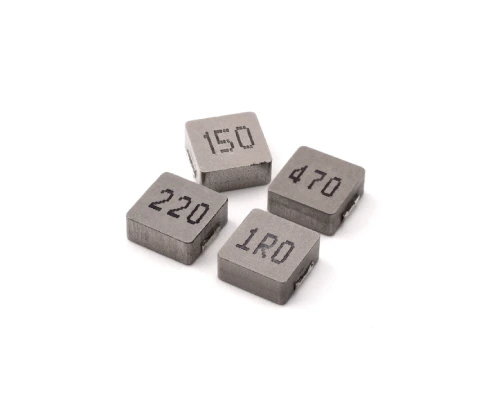
100Ω Inductor (10μH): A Master of Low-Frequency Filtering and Ripple Suppression
The value of 100 corresponds to 10 μH; since this is higher than the previous two values, it generates greater inductive reactance at the same frequency. Consequently, it is more effective at suppressing low-frequency noise and performs better in energy storage and filtering applications.
A trade-off associated with high-inductance components is that, compared to low-inductance counterparts, they are typically larger in size and exhibit poorer high-frequency response; consequently, they are generally not used for core power delivery at extremely high frequencies but are instead primarily employed for filtering at the power input and output stages.
Typical application scenarios include the following:
The power adapter and fast charger output filter cleans up the ripple generated by the switching power supply, providing a stable DC power to the downstream equipment.
EMI filtering at the power input of industrial control boards and equipment suppresses low-frequency interference from the power grid.
Low-frequency noise suppression for automotive electronics, such as power input filtering for in-vehicle infotainment systems.
In ordinary audio equipment, power supply filtering with a 10μH inductance can better filter out low-frequency ripple, resulting in cleaner audio output and reduced background noise.
While working on an industrial controller project, I encountered an issue where the power input failed the EMC low-frequency radiated emission test. Replacing the original 4.7μH inductor with a 100μH inductor allowed the unit to meet the standard immediately, yielding a remarkable improvement.
Finally, here are a few suggestions on how to choose the right solution. These are experiences I’ve gained from years of project practice and can save you a lot of time:
Match the frequency first, then consider the inductance value: remember this principle and you won’t go wrong. Low inductance values (such as 2R2) are more suitable for high-frequency switching circuits, while high inductance values (such as 100) are more suitable for low-frequency filtering. Do not confuse the two; forcing a 10 µH inductor into a high-frequency CPU power supply circuit will inevitably lead to stability issues.
Don’t just look at the nominal inductance; the current parameter is the key: No matter which model you choose, you must check the saturation current (Isat) and temperature rise current (Irms) on the datasheet. The actual operating current must be lower than the minimum of these two parameters; otherwise, the inductor will saturate, the inductance will drop significantly, and the circuit will become unstable.
Distinguishing between the markings on inductors and resistors is crucial: for a resistor, the nominal value “100” represents 10Ω, whereas for an inductor, it represents 10μH. Beyond markings, they can also be distinguished by package and layout; given the same number of pins, inductors are typically thicker than resistors and are usually located on power traces, making them easy to identify.
In fact, the 4R7, 2R2, and 100 inductors are among the most commonly used specifications for surface-mount (SMD) inductors; once you understand the labeling conventions and the differences in their application scenarios, selecting the right one becomes very straightforward. If your project happens to encounter these options, you might want to compare them with the scenarios in this article. Choosing the right option can save you a lot of debugging time.
If you have any further questions regarding inductor selection, please feel free to contact us via email at info@smdinductor.com.