Ferrite beads are anti-interference electronic components with ferrite material as the core. They are mainly used to suppress high-frequency noise and electromagnetic interference (EMI/RFI) while allowing DC or low-frequency signals to pass through normally. Its core function is to convert high-frequency noise energy into thermal energy for dissipation, rather than storing energy as an inductor does. It is widely utilized in communication equipment, consumer electronics, power supply systems, and high-speed signal lines.
1. Core Characteristics of Ferrite Beads
Working Principle: Utilizing the hysteresis loss and eddy current loss of ferrite materials at high frequencies, high-frequency noise energy is converted into heat energy and dissipated, rather than being reflected or stored like energy in an inductor.
Equivalent Circuit: It can be modeled as a composite network consisting of an inductor (L) and a resistor (R) connected in series, and then a parasitic capacitance (C) connected in parallel.
Frequency Response Characteristics:
– Low frequency range: Inductive, impedance is mainly composed of inductive reactance;
– Mid-to-high frequency range (target operating area): Resistive component dominates, effectively absorbing noise;
– Above the self-resonant frequency: Capacitive, filtering capability decreases.
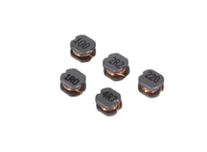
Units: Nominal in ohms (Ω) (e.g., 600Ω @ 100MHz), not in Henrys (H).
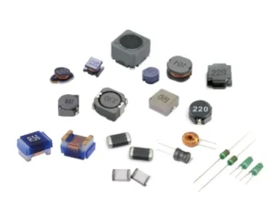
2. Main Types and Structures of Ferrite Beads
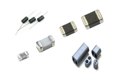
By Package Type:
– Surface Mount (SMD; e.g., 0402, 0603, 0805, etc.)
– Through-hole (Axial/Leaded, Standard Cylindrical)
By Material:
– Manganese-Zinc (Mn-Zn) Ferrite: Suitable for low frequencies (<30 MHz)
– Nickel-Zinc (Ni-Zn) Ferrite: Suitable for high frequencies (>100 MHz)
By Application Scenario:
– General Purpose, High-Current, Spike Suppression (used to suppress transient interference)
3. Key Selection Parameters for Ferrite Beads
Impedance Value (e.g., 100Ω @ 100MHz): Determines high-frequency suppression capability.
Rated Current (IRAT): Prevents magnetic saturation; it is recommended that the operating current be ≤ 20%–50% of the rated current.
DC Resistance (DCR): The lower, the better, to minimize voltage drop and power dissipation.
Impedance-Frequency Curve (Z-R-X Curve): Must match the target noise frequency band.
Self-Resonant Frequency (SRF): The operating frequency should be lower than the SRF.
4. Main Applications of Ferrite Beads
Suppressing high-frequency noise on power lines: Commonly used in switching power supplies, DC-DC converters, and the power input terminals of digital circuits to filter out switching noise, ripple, and high-frequency interference, preventing them from propagating to other circuit components.
Suppressing high-frequency interference on signal lines: Applied to clock lines, high-speed data lines (such as USB, HDMI, DDR memory interfaces), radio frequency (RF) circuits, etc., to absorb high-order harmonics and EMI, and improve signal integrity.
Electrostatic discharge (ESD) absorption: It can absorb transient electrostatic discharge energy and protect sensitive electronic components from damage.
Common-mode and differential-mode noise suppression: It can be used as part of a common-mode choke on power lines or communication cables to suppress common-mode interference; it can also be used alone for differential-mode noise filtering.
Digital-to-analog circuit isolation: In mixed-signal PCBs, it is often placed between digital ground and analog ground to suppress digital switching noise coupling into the analog section while maintaining DC continuity.
5. Typical Application Scenarios of Ferrite Beads
Consumer Electronics: Power and signal circuits in mobile phones, tablets, and laptops.
Communication Equipment: High-frequency circuits in routers, base stations, and 5G devices.
Automotive Electronics: In-vehicle infotainment systems, ADAS, and power management modules.
Industrial Control: PLCs, sensor interfaces, and motor drivers.
Medical Equipment: Instruments sensitive to EMI, such as ECG machines and ultrasound devices.
⚠️ Note: Unlike inductors, ferrite beads are energy-dissipating devices specifically designed to absorb and dissipate high-frequency noise; inductors, conversely, are energy-storing devices used for filtering or resonance. The two are not interchangeable.
Key Features Overview
Impedance is measured in ohms (Ω) and represents the impedance value at a specific frequency (e.g., 100 MHz)—for instance, “600Ω @ 100 MHz.”
The equivalent circuit consists of a resistor (R) and an inductor (L) connected in series; at low frequencies, it exhibits inductive characteristics, whereas at high frequencies, it behaves as a resistor and dissipates energy.
Magnetic saturation must be avoided: under high-current conditions, permeability decreases, resulting in degraded filtering performance. It is recommended that the operating current not exceed 20% to 50% of the rated current.
It is typically used in conjunction with decoupling capacitors to form a low-pass filter; however, one must be mindful of the potential for LC resonance and, if necessary, add a damping resistor.
When selecting components, please refer to the manufacturer’s impedance-frequency curves and choose based on parameters such as operating frequency, current, and package size. Major suppliers in this field include Murata Manufacturing, TDK, and Sunlord Electronics.